
Rainbow Serpent Festival has become my annual ritualistic ‘turn the phone off, dance till my legs hurt, catch up with old friends, meet new ones, reflect and re-focus’ 21st century pilgrimage. It’s also a great place to check out fantastic visual art, and even if you’re not part of the official program there’s plenty of opportunity to roll your own. As the photographer Bill Cunningham once said:
The best fashion show is definitely on the street. Always has been, and always will be
Apparently this is the era of wearable tech, and with addressable colour LEDs coming down in price and up in brightness, density and packaging, let’s make a sound-reactive LED techno hat. You can never have too much eye candy on the dance floor.
The job was threefold:
- Get the raspberry pi driving the LED array
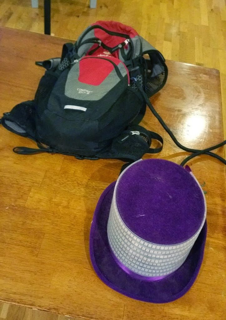
- Battery power everything from a small backpack
- Make it remote-controllable, preferably from a phone or other WiFi device
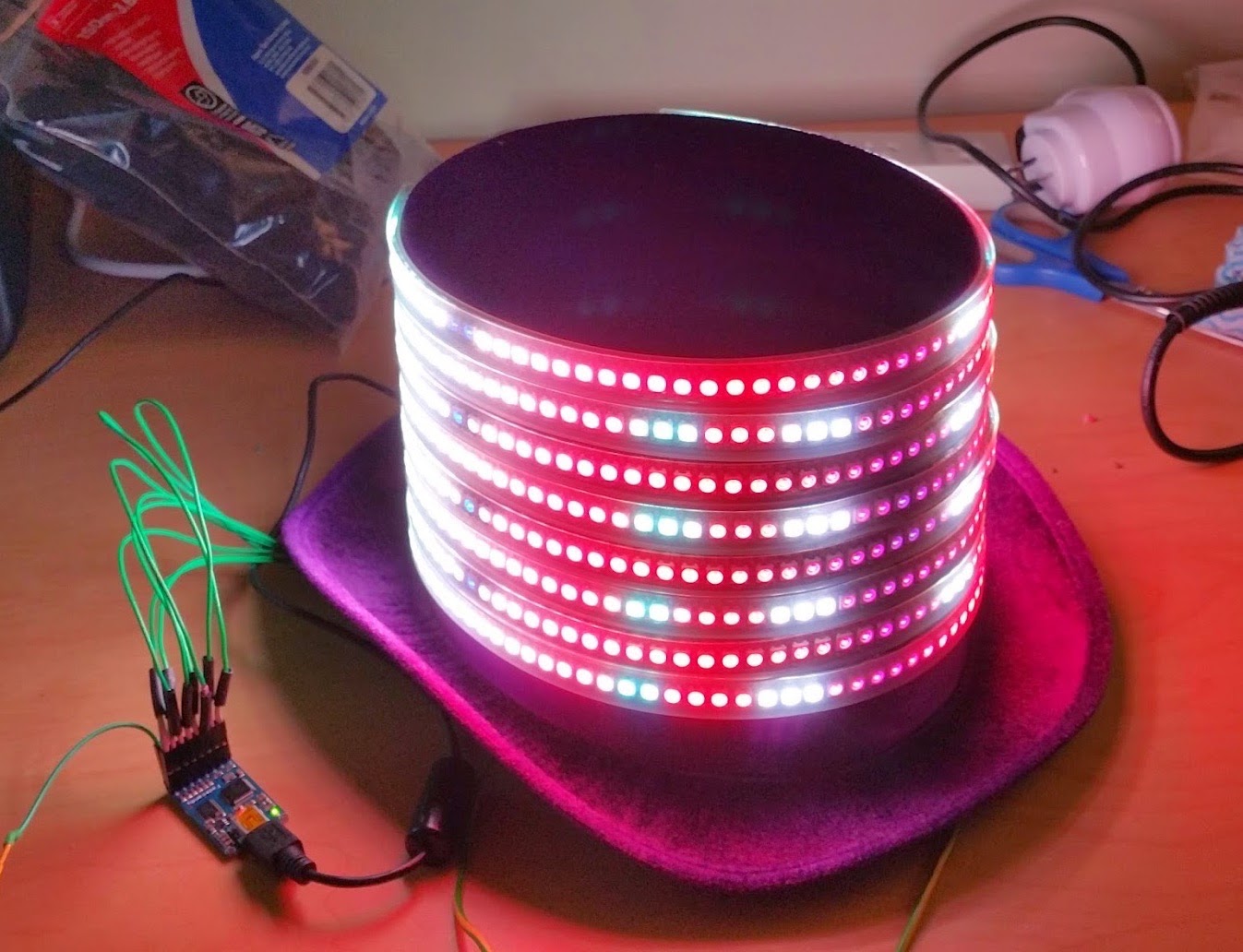
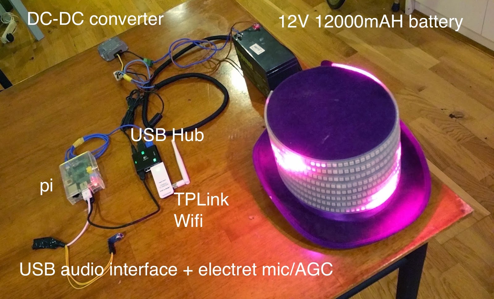
Pictures during and after construction
Videos
Ingredients
- One (awful) hat. This one cost me about AUD$15 on eBay and is as horrendously purple as it looks
- Lots of epoxy adhesive. It’s the only stuff I could get to stick the LED silicone tubes.
- Usual craft and electronics bench equipment
Electronics Components
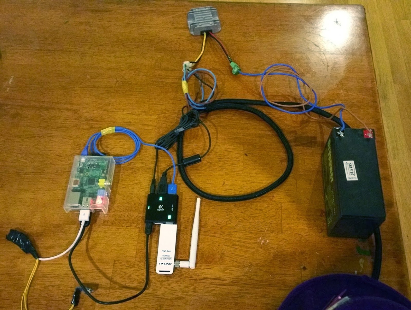
- Raspberry Pi (running Raspbian)
- Fadecandy USB 8-channel dithering WS2812 LED driver:
- 8x WS2812B 1m 144 RGB LED strips encapsulated in silicone (Alibaba)
- -Cheap USB audio interface that can be modded (covered later):
- -Electret microphone + auto gain control:
- TP-Link TL-WN725N 802.11G/N USB adaptor
- A cheap USB2 hub I had kicking around, remote 5V powered
Raspberry Pi
The Pi is easily available and cheap. I wanted to use the Beaglebone but the order didn’t arrive in time. Once overlocked to 1GHz performance ended up being adequate.
The Pi boots into Debian from an SD card. The TP-Link dongle is run as an access point using hostapd + udhcpd. There are plenty of guides on the web about getting this working. I went with the TP-Link as unlike other adaptors the Debian hostapd binary is compatible and I gave up rebuilding the drivers/hostapd after running into a pile of kernel header issues.
All that remained were the installation of the GCC toolchain (build-essential) for building fade candy and the JVM for PixelController. I hijacked an existing init.d script to start both of these at boot.
Pi Audio Input
The Pi doesn’t have an analog audio input. The C-media USB dongle is USB audio class-compliant and worked fine. I had to bastardise the one you can see in the picture, soldering a 100uF electrolytic capacitor across the input pins and borrowing +5V from the USB bus. This was due to the DC offset of the AGC output and it’s power requirements. The adafruit product page for this device discusses this. I set the AGC to 40dB and left it there. Input gain in ALSA was set to ~75.
Software:
Fadecandy Open Pixel Control Server
This communicates with the Fadecandy over USB and exposes an Open Pixel Control socket to where we will send the LED data. It’s also capable of re-mapping the pixel array to compensate for snaked or other non-sequential wiring. This wasn’t needed, but I did take advantage of the colour and gamma correction for the array.
I could have driven the LEDs directly from the Pi via the DMA hack, or added a DMX512 (RS422) output and used an off-the-shelf driver board, but the Fadecandy does so much more. Doing temporal dithering and gamma correction/key frame interpolation in 16bpp colour I’ve found that it handles low brightness levels/fades/transitions in a much more subtle and effective way than I see by bit-banging a 24-bit colour buffer straight into the LEDs.
PixelController LED matrix software
This Java application generates the eye candy. It has a few different visual generators, effects and mixers. It’s also cross-platform due to a Java codebase. Whether the Pi would be up to the task was questionable, but given that the Pi now sports official support from Oracle for the platform in the form of an ARM hard-float JVM (there’s a lot of floating point code in PixelController) I was prepared to give it a shot.
I had grand plans to roll my own effects engine, but time was against me. PixelController had most of what I needed; flexible effects generation/preset control, headless ‘console’ mode running on the Pi and OSC remote control.
PixelController doesn’t talk OPC out-of-the-box nor can it talk natively to the FadeCandy via libUSB, so I wrote a patch to get it to talk to the FadeCandy OPC server over TCP. At the time of writing the patches haven’t been merged, but it’s here on Github if you want to try it. (Edit: It was merged). There’s no multi-panel support or gamma/colour-correction offload support, but it’s good enough for this scenario.
TouchOSC was used to remote control PixelController.PixelController even contains a layout file. I tweaked the layout a bit for my own preference but this part was a lot easier than expected!
TouchOSC/PixelController find each other using mDNS; no manual config was required.
LED Array Construction
The Fadecandy has 8 outputs, each of which can drive 64 LEDs
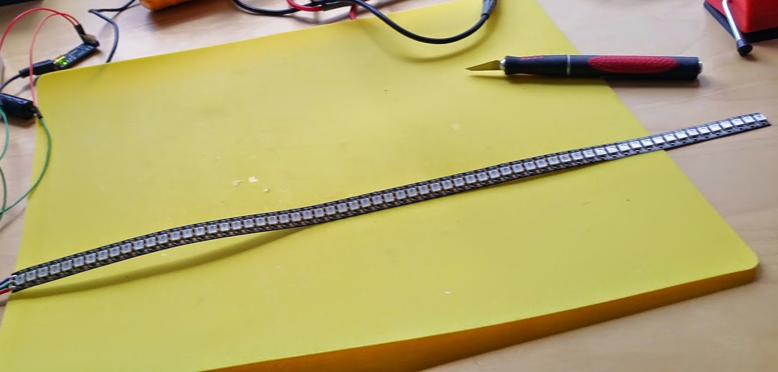
I received 4 strips of 144 LEDs. They look like this with the silicone shielding removed.
A bit of simple math, cutting and soldering transforms these into 8×64 strips with 8×8 strips left over. These will be found a home on another project.
Power Considerations
Each WS2812 LED apparently draws 60mA @ 5V at full brightness, but I don’t trust this given they’re Ali Baba specials. Firing up some test code and a current meter I got these values:
Nominal Value:
100% on 64 LEDs -> (60/1000) * 64 = 3.84A @5V
Tested Values:
50% on 64 LEDS -> 1.7A @ 5V
100% on 64 LEDS -> 3.3A @ 5V
They’re pulling a bit less current than expected, and the power curve appears fairly linear.
Scaling this up:
512 LEDS (8*64) -> 26.4A @ 5V (132W) @ 100% brightness
Wow, that’s pulling quite a lot of power, and this thing is going to be running off batteries.
Fortunately, a 12V lead-acid battery will be used with a DC-DC step-down converter for which we get the more conservative 11A @ 12V. A lead acid battery was chosen due to the high output current current handling capabilities. It was not chosen for it’s low weight! A few Li-Po packs were investigated but getting high output current at a sensible price wasn’t proving fruitful.
We also need to take into account the fact that this peak load will very rarely be achieved in practise. In practise it was found that the LEDs are extremely bright and running them at full power was unnecessary most of the time. Unfortunately this meant losing dynamic range in the LED output signal by scaling to 50% or 75% most of the time.
The step-down transformer I used (not the 100W one that I ordered and didn’t receive) was rated to 25W RMS. Peak wasn’t quoted but we can assume its 25/.707= ~ 35W. As I was running 50% max brightness most of the time and given none-white output, I didn’t expect to experience (nor did I) any problems running with this.
Wiring for power
18AWG power wire from LEDs is rated to 16A (up to 300V typically)
2 of these run in parallel from the transformer rates us to 32A @ 5V, which is more than plenty.
In the end I skimped in construction of this given the under speccing of the DC-DC transformer.
Room for improvement?
Pi -> Beaglebone
Performance from the Pi was ok, but it felt underpowered. Effect frame rate was lower than I was hoping for. I expect moving to the Beaglebone with the ARMv7 core with VFP + NEON support in addition to the higher clock rate will yield better results. I’m sure further code optimisation and making use of the GPU in PixelController would have helped too.
Power
The 100W 24V-5V stepdown transformer didn’t arrive in time. This would have required two 12V batteries wired in series and beefing up of the 5V cabling.
Remote Display
The wearer can’t see what the damn thing is doing. Either get an extrovert friend to wear it while you press the buttons, or the remote app needs a remote view.
Actually, the whole thing would run just fine on a phone. Android supports USB OTG host-mode so could drive the fadecandy directly.

I've just started writing some basic 'effects' using node js, to run on a raspi and fadecandy board. PixelController looks extremely interesting though, I will check it out (and your patch). Thanks for shareing
Note: some of the links in this page point to evernote.com. You may want to fix them 🙂
LikeLike
Thanks Greg! And sorry for the late reply. I've actually been meaning to migrate over to WordPress, but, time… you know 🙂 I think the patch got integrated into PixelController, so it should work as is. I actually found for a more recent project that Python+CPython for the math worked a treat on the Pi2. Hope you got your project going.
LikeLike
Hey Robert,
First off, cool project! I was trying to set up something vaguely similar, but PixelController doesn’t seem to have integrated that patch.
LikeLike
Check the development branch:
https://github.com/neophob/PixelController/commits/develop
That project seems to be very inactive now anyway. Did you get anywhere with another solution?
LikeLike